Reflow Soldering
Reflow Soldering
This tutorial explains the use of the Techno Print HA-02 reflow oven. A simple and practical step-through procedure is suggested to limit the effort for the first time user. The user manual for the oven can be downloaded from Media:Rfo-ha02-manual.pdf, while a quick search on the web for "reflow soldering" should give some basic knowledge about reflow soldering. The oven should be placed inside a fume cupboard to draw unhealthy and annoying solder fumes away from the person soldering.
When to use it?
Do I really need this oven? Many components can easily be soldered by hand with better results. In general: if you can do it by hand, forget the oven. Some components do not have accessible pads, or they are simply too densely placed for hand soldering. This is when the oven comes in handy, although at the cost of some time and effort. Another example is when you repeat the same soldering process for several identical PCBs, as reflow soldering is a quite fast process once the time and temperature settings are known.
Step 1 - Creating a Time and Temperature Profile
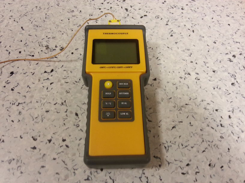
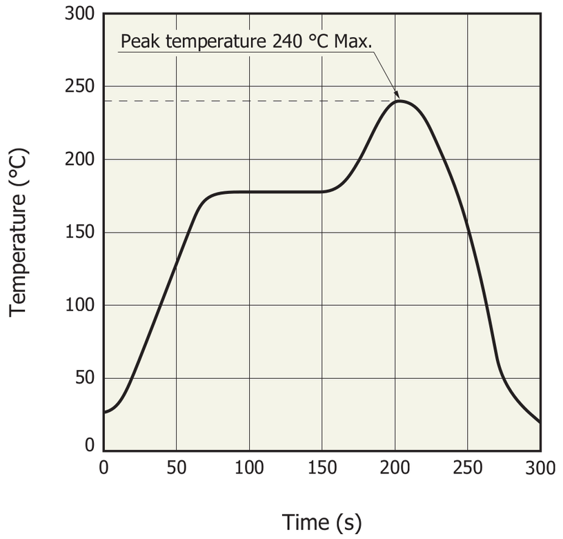
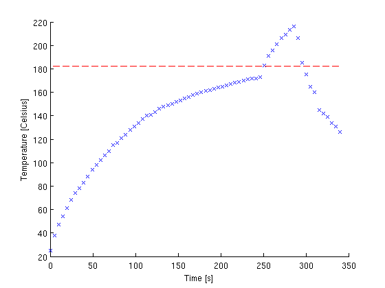
The process of soldering is divided into two zones - "preheat" and "reflow". Time and temperature has to be specified for both these zones to obtain the desired thermal profile, and the settings will differ from PCB to PCB. Temperature can be monitored by attaching a thermocouple to the PCB with Kapton tape. The desired thermal profile is then iteratively found by running the reflow process on the unpopulated PCB several times while adjusting the time and temperature settings of the oven.
Figure 1: Thermocouple used for temperature measurements
Figure 2: Recommended solder profile for Hamamatsu MPPC (From Hamamatsu S10362-11 series datasheet)
Figure 3: Measured solder profile during reflow soldering
Step 2 - Apply Solder Paste
When a reasonable thermal profile is found, the components are attached to the PCB by the use of solder paste. Solder paste can be applied from the dispenser by hand, and it is a good idea to try this a few times on an old PCB to get the right amount of paste. Avoid mixing different solder pastes, and remove any old solder tin from the PCB and the components before applying the paste. Then place the components.
Step 3 - Do it!
You are now ready to do the actual reflow process. Since you now are familiar with the thermocouple, it might be a good idea to attach it to the PCB while doing the actual reflow soldering. In this way you can document that you actually followed the thermal profile when doing the real thing.
Thermal Shielding
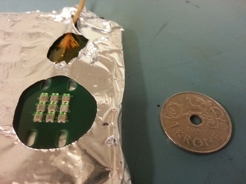
If you have a PCB that is already populated, you might want to thermally shield some or all components. This can be done by wrapping the PCB in aluminum foil with a window where you want to solder. Pay attention to the thermal profile in your window, since the foil will make it harder to heat the PCB.
Figure 4: Example of reflow soldering of MPPCs with thermal shielding and monitoring


