Cadence Testbench
Simulate with corner cases
To simulate with the corner cases in the fabrication process you have to add the corner files provided in the design kit.
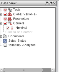
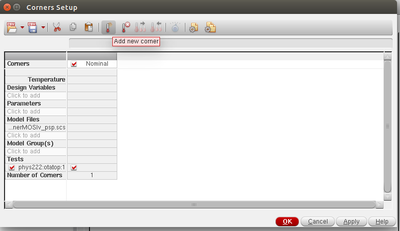
Choose "Click to add corner"
"Click to add" the model files you need.
Ex. The corner files for the MOS transistor in IHP130nm process is located in $IHP_TECH/tech/SG13_MOS/library/spectre/cornerMOSlv_psp.scs
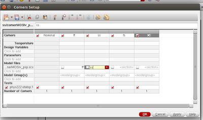
After adding the model files needed proceed by adding multiple corners:
The model files contains sections with the different corners. Choose sections and make sure you enable the section "tick box" and name the corner with a corresponding name:
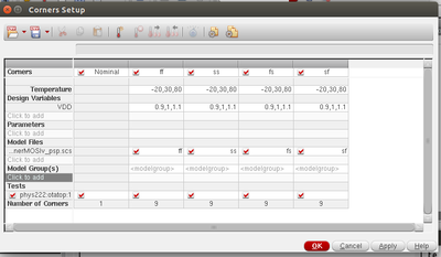
The corners setup also makes it possible to simulate for different temperatures or design variables like VDD and transistor length. Ex. test for three different temperatures with comma as separation: -20,30,80
To the do the simulation take a look at the "Data View" tab again. Make sure you have selected the corners, the desired test and global variables, and that they have the correct value.
Then at the drop down menu in the toolbar, where stand "Single Run, Sweeps and Corners" click the light green play button. This will run the selected test, with your parameter values and selected corners.
Wait for the simulation to complete, and then you can plot different corners, or use the "Plot All" button to get all corners plotted.


