Bitvis UVVM VHDL Verification Component Framework: Difference between revisions
No edit summary |
No edit summary |
||
| Line 108: | Line 108: | ||
=== Add support process for clock generation === | === Add support process for clock generation === | ||
We now have to add a support process that controls the clock. This has to allow enabling/disabling from the test sequencer. We add the following before "begin" in our architecture: | |||
<pre> | |||
-- Added for clock generation | |||
signal clock_ena : boolean := false; | |||
constant C_CLK_PERIOD : time := 10 ns; | |||
procedure clock_gen( | |||
signal clock_signal : inout std_logic; | |||
signal clock_ena : in boolean; | |||
constant clock_period : in time | |||
) is | |||
variable v_first_half_clk_period : time := C_CLK_PERIOD / 2; | |||
begin | |||
loop | |||
if not clock_ena then | |||
wait until clock_ena; | |||
end if; | |||
wait for v_first_half_clk_period; | |||
clock_signal <= not clock_signal; | |||
wait for (clock_period - v_first_half_clk_period); | |||
clock_signal <= not clock_signal; | |||
end loop; | |||
end; | |||
</pre> | |||
Our clock can now be activated from the test sequencer (this will be added in the next step): | |||
<pre> | |||
clock_gen(clk, clock_ena, 10 ns); | |||
clock_ena <= true; | |||
</pre> | |||
=== Add test sequencer process === | === Add test sequencer process === | ||
Revision as of 14:11, 27 January 2016
-- Copyright (c) 2016 by Bitvis AS.  All rights reserved.
-- You should have received a copy of the license file containing the MIT License (see LICENSE.TXT), if not,
-- contact Bitvis AS <support@bitvis.no>.
-- UVVM AND ANY PART THEREOF ARE PROVIDED "AS IS", WITHOUT WARRANTY OF ANY KIND, EXPRESS OR IMPLIED,
-- INCLUDING BUT NOT LIMITED TO THE WARRANTIES OF MERCHANTABILITY, FITNESS FOR A PARTICULAR PURPOSE AND NONINFRINGEMENT.
-- IN NO EVENT SHALL THE AUTHORS OR COPYRIGHT HOLDERS BE LIABLE FOR ANY CLAIM, DAMAGES OR OTHER LIABILITY,
-- WHETHER IN AN ACTION OF CONTRACT, TORT OR OTHERWISE, ARISING FROM, OUT OF OR IN CONNECTION WITH UVVM.
--========================================================================================================================
Introduction
Bitvis UVVM VVC Framework is a complete framework for making VHDL testbenches for verification of FPGA and ASIC desing. You can download the complete code-base, examples and simulations scripts from the Bitvis web page.
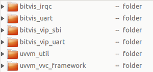
What's in the folders?

The download includes severals folders:
- bitvis_irqc - example VHDL design + testbench
- bitvis_uart - example VHDL design + testbench
- bitvis_vip_sbi - Verification IP(VIP) for simple bus interface(SBI)
- bitvis_vip_uart - VIP for UART TX and RX
- uvvm_util - UVVM utility library - sufficient for simple testbenches
- uvvm_vvc_framework - Framework for more advanced tutorials
IRQC

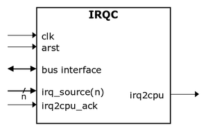
The provided example VHDL design is a simple interrupt controller with several internal registers, a bus interface and some input and output signals.
Testbench creation
Copy the folders bitvis_irqc, bitvis_vip_sbi and uvvm_util to another location before editing the files.
Generate TB entity with DUT instantiated
Our TB entity can in many cases be generated from several tools. Notepad++ (among other) supports plugins that enables copying an entity and pasting it as an instantiation, and also as a complete testbench template. However, we will change some of our signals so that they fit the VIP SBI BFM. The signals to and from the CPU will be converted to t_sbi_if record, which is a type that includes all the SBI signals (cs, addr, rd, wr, wdata, ready and rdata).
--Standard libraries
library IEEE;
use IEEE.std_logic_1164.all;
use IEEE.numeric_std.all;

-- Libraries used for string handling in UVVM
library STD;
use std.env.all;

-- Obviously the UVVM library
library uvvm_util;
context uvvm_util.uvvm_util_context;

-- We will use this library later when implementing the Bus Functional Model
-- Includes among much else the record type t_sbi_if and many functions
-- If other buses are used, you will have to change this library
library bitvis_vip_sbi;
use bitvis_vip_sbi.sbi_bfm_pkg.all;

-- This file includes definitions of everything from registers to record types
use work.irqc_pif_pkg.all;


-- Test case entity
entity irqc_tb is
end entity;

-- Test case architecture
architecture func of irqc_tb is

  -- DSP interface and general control signals
  signal clk           : std_logic  := '0';
  signal arst          : std_logic  := '0';
  -- CPU interface
  -- t_sbi_if is from the verification IP SBI
  -- init_sbi_if_signals initialize the inputs to 0 and the outputs to Z
  signal sbi_if : t_sbi_if(addr(2 downto 0), wdata(7 downto 0), rdata(7 downto 0)) := init_sbi_if_signals(3, 8);

  -- Interrupt related signals
  signal irq_source    : std_logic_vector(C_NUM_SOURCES-1 downto 0) := (others => '0');
  signal irq2cpu       : std_logic := '0';
  signal irq2cpu_ack   : std_logic := '0';

begin

  -----------------------------------------------------------------------------
  -- Instantiate DUT
  -----------------------------------------------------------------------------
  i_irqc: entity work.irqc
    port map (
    -- DSP interface and general control signals
        clk             => clk,
        arst            => arst,
    -- CPU interface
        cs              => sbi_if.cs,             -- NOTICE THE SIGNALS ARE NOW SBI_IF
        addr            => sbi_if.addr,
        wr              => sbi_if.wr,
        rd              => sbi_if.rd,
        din             => sbi_if.wdata,
        dout            => sbi_if.rdata,
    -- Interrupt related signals
        irq_source      => irq_source,
        irq2cpu         => irq2cpu,
        irq2cpu_ack     => irq2cpu_ack
        );

end func;
Add support process for clock generation
We now have to add a support process that controls the clock. This has to allow enabling/disabling from the test sequencer. We add the following before "begin" in our architecture:
-- Added for clock generation
  signal clock_ena  : boolean := false;

  constant C_CLK_PERIOD : time := 10 ns;

  procedure clock_gen(
    signal   clock_signal  : inout std_logic;
    signal   clock_ena     : in    boolean;
    constant clock_period  : in    time
  ) is
    variable v_first_half_clk_period : time := C_CLK_PERIOD / 2;
  begin
    loop
      if not clock_ena then
        wait until clock_ena;
      end if;
      wait for v_first_half_clk_period;
      clock_signal <= not clock_signal;
      wait for (clock_period - v_first_half_clk_period);
      clock_signal <= not clock_signal;
    end loop;
  end;
Our clock can now be activated from the test sequencer (this will be added in the next step):
clock_gen(clk, clock_ena, 10 ns);
clock_ena <= true;
Add test sequencer process
Open up Questa/Modelsim
Change directory to the script folder (obviously change to your folder.....):
cd ~/phys321/bitviswiki/bitvis_irqc/script
do compile_and_sim_all.do

